Printing and Assembling the Fuselage Parts for the Mini Extra 300
- Robareeno

- Jul 18, 2022
- 5 min read
Updated: Aug 26, 2023
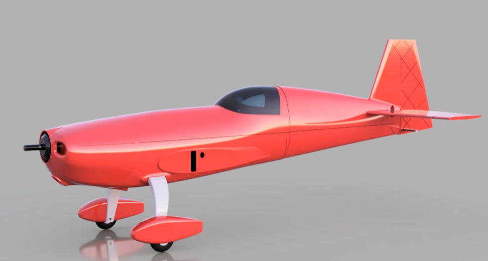
This blog is for the construction of the fuselage for the mini Extra 300. Note, this blog page is for the paid version of this plane with the full fuselage, not the profile version.
Important Note on Single Wall Printing:
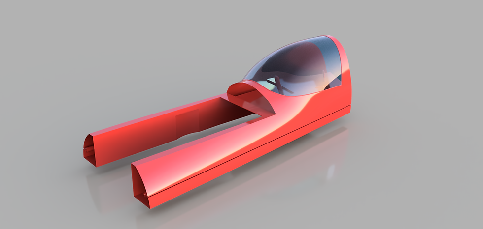
Lightweight PLA is some fabulous material for making airplanes. As with all materials, however nothing is perfect. One of the drawbacks to LWPLA is that due to its foaming nature controlling stringing is nearly impossible at print head retractions. A typical printing approach will yield an awfully messy part. So we have to think outside of the box. If you cannot control stringing at retractions, eliminate retractions altogether. You will notice that the parts supplied in this model are actually full solid bodies. See the image below:

Unless you want a hefty non flyable paper weight, you will want to use the single wall, "vase mode" settings in the Cura slicer. This setting creates only an outer shell of the part. All of the parts are designed in such a way so that the print head can complete an entire layer in one beautiful continuous pass without ever performing a retraction.
If the settings are supplied correctly, the only anomaly in the print will be the Z seam. My preference is to keep the z seam all in the exact same place, again to control retraction. Also, any problems are easily sanded in one tiny spot on the part when complete. Any place on a part where a hole is to occur would actually break the continuous flow of filament introducing little boogers and strings. To control this, each part has a clearly marked indention at places where holes are to exist. Quick work with an Xacto knife makes the hole actually happen and the part stays perfectly clean. Attached is a video explanation from my youtube channel:

Empennage:
Print setting: "Single Wall LWT"
Notice the two printed tubes on each side of the part. This exists through the whole length of the model for the purpose of bonding a single run of upholstery thread, or even better Kevlar thread through the model introducing tension. Both can be commonly sourced from a local fabric store. In truth, Upholstery thread is more than adequate for this size of model.
Tip" How do you push a piece of thread all the way through this part? Roll more than enough thread to run down both sides of the model with length to spare. Pull the thread taught and straight. Now using something like a plastic baggy place several drops of Ca glue on it and run it up and down about a 1 foot length of the end of the string. Let it cure, then do it a second time. Once dried snip the end off with scissors. You have just created a semi rigid needle that can easily thread down the hole. Tie a double knot in the opposite end of the thread. now starting from the elevator side of the fuselage part thread the entire length through snugging the not up to the back of the empennage part. Carefully use only a small amount o CA glue on the not to secure it to the fuselage part. You can now fish the thread through the Upper fuselage part, and then the firewall, motor mount. Once this is done on both sides, you may now actually apply tension to the thread snugging the parts together. Again apply only a small amount of CA glue this time to the firewall side of the thread to bond it to the body while under tension. Be careful to not use too much. Once this is done, carefully align the fuselage parts into proper position and CA glue them together. Then go back and apply a generous amount of CA glue down the thread hole to bond the thread all the way through the body.
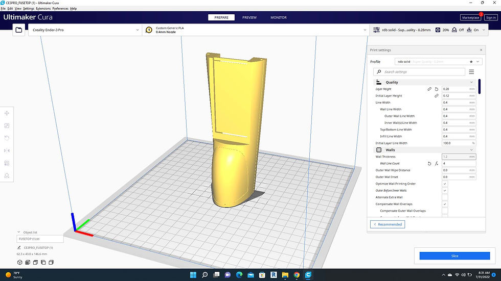
Upper Fuselage:
Print setting: "Single Wall LWT"
Printer orientation as shown below.
Supports are not required.
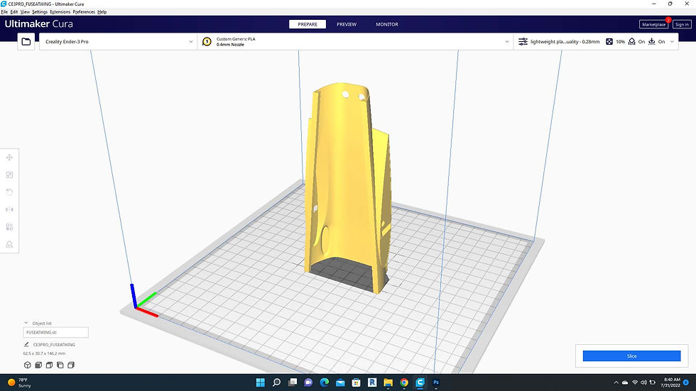
Lower Main Fuselage:

Printer orientation as shown below.
Supports are not required.
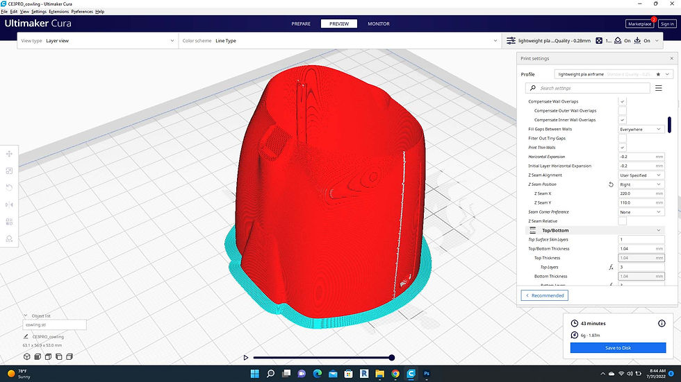
Cowling:
Print setting: "Single Wall LWT"
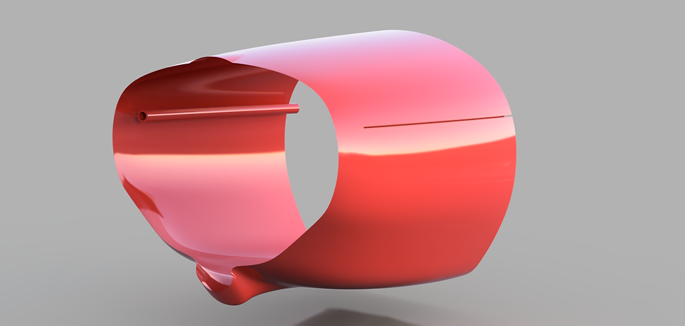
Printer orientation as shown below.
Supports are not required.
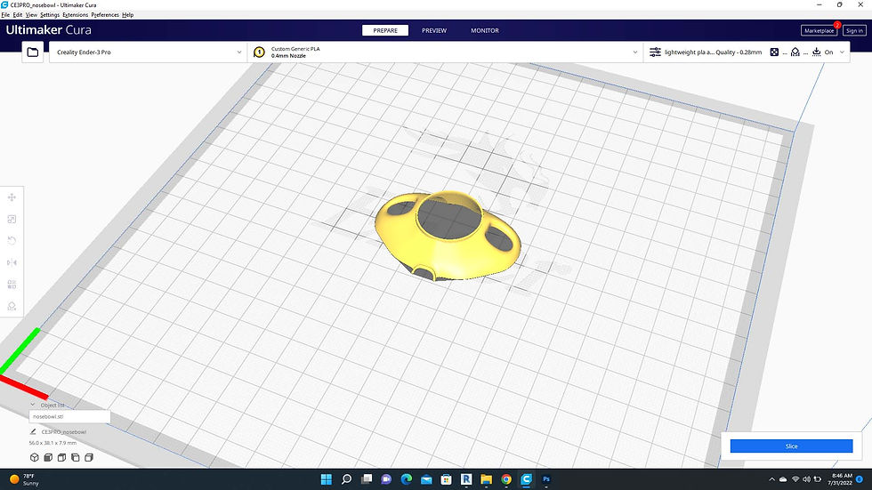
Nose Bowl:
Print setting: "Solidbody LWT"
Supports: On.
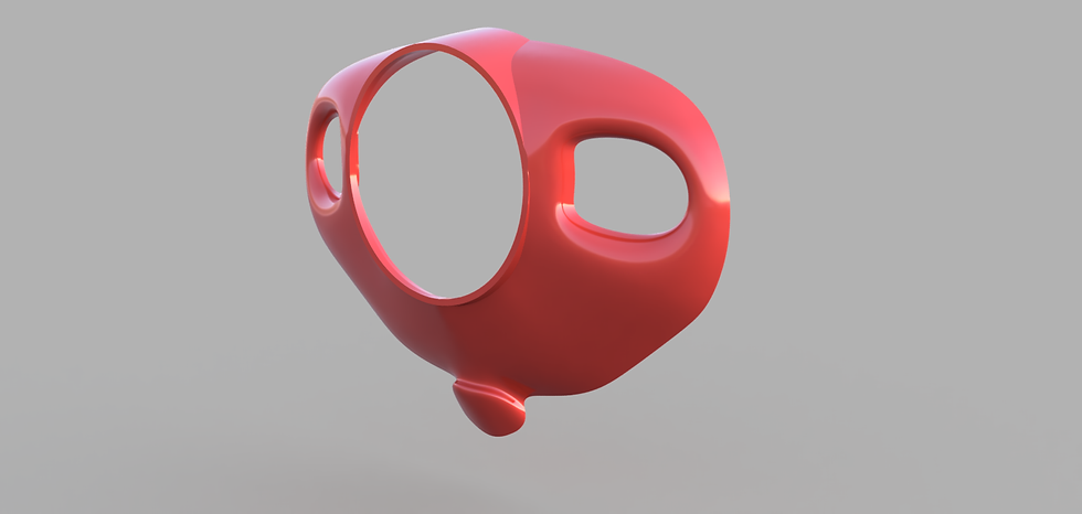
Printer orientation as shown below.
Supports are required.
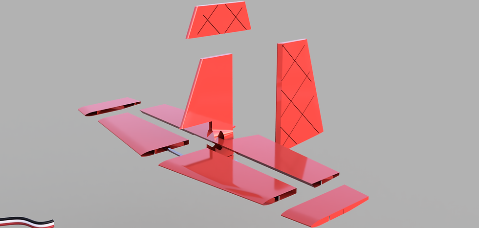
Tail Feathers exploded view:
Print setting: "Single Wall LWT" Note in the graphic that there is a small 1mm carbon rod between the horizontal stabilizers. I no longer feel that this is necessary as there also is one reinforcing the elevator.
Vertical Stabilizer Printer orientation as shown below.
Supports are not required.
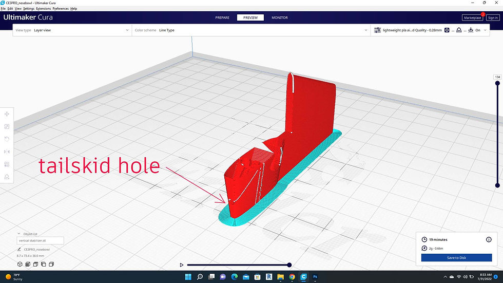
Note that the tail skid will be a small 1mm carbon fiber rod that is placed in the tiny hole at the arrow indicated above.
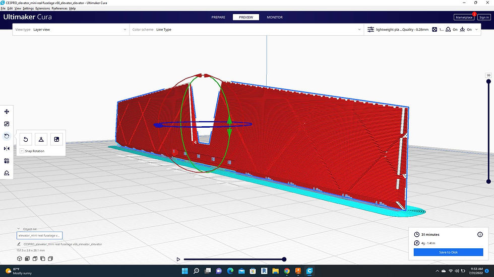
Elevator Printer orientation as shown below.
Supports are required.
The tips of the elevator have been split from the main elevator to facilitate easy printing in the orientation shown. Tip, if you would rather print the assembly as one single part you can load the elevator and the elevator tips into Cura. Select all three models then right click. From the pop up window you can then select "merge models" this will group the assembly together as it existed in the original model. It can now be printed as a single part. if prefered. This will greatly increase printing time, however.
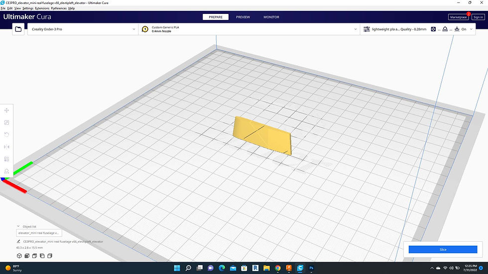
Elevator Tip Printer orientation as shown below.
Supports are not required.
Tip: It is tempting to put multiple small parts together on the build plate. You can certainly do this, but lightweight PLA will tend to string between parts. You will just have a little clean up to do.
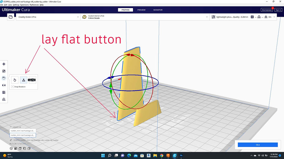
Rudder Printer Orientation as Shown Below.
Supports are not required. Make sure to use the rotation "lay flat" button to orient the rudder to the build plate.
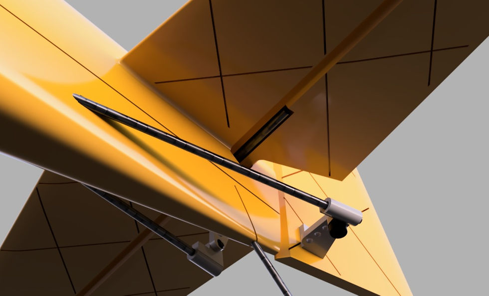
View of Empennage assembly from below illustrating the carbon rod required to reinforce the elevator, as well as both the rudder and elevator control horns, 1mm carbon pushrods, and 1mm carbon tailskid. This model is so small that the horns may be simply CA glued into the proper position. The pushrod end is designed to be fastened to the horn with a 2mmx4mm Allen screw. Alternately I have found that eyeglass repair screws work great in this location. The pushrod end will be CA glued to the pushrod in the proper position once servos are installed and trims and centering of the servo have been verified. Use the old rule, "measure twice, glue once." You may opt for an adjustable pushrod and clevis pin but I have found them to be far heavier that this setup. With a model of this size weight is very critical.
Hatch:
Print setting: "Single Wall LWT"
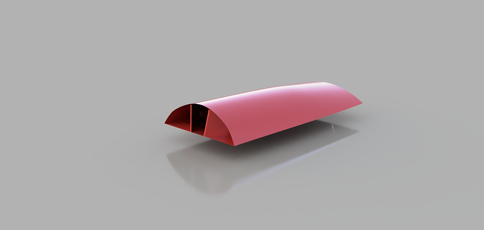
Note that there is a small tab called "bhatchtab.stl" that must be printed as a solid body. It will be adhered using CA glue right between the inner supports of the picture above. This tab slides under the canopy frame when inserting the hatch on the model.
Conclusion: That is it for the Fuselage! Check the main blog here for the next steps. Feel free to reach out to us with any questions. We will attempt to clarify the construction blog including your input as much as possible. Also please check out or new community forum. Feel free to post pics, ask questions, or help others.

Comments