Landing Gear and Wing
- Robareeno

- Nov 8, 2021
- 3 min read
Updated: Aug 26, 2023
How to print and assemble the Fokker DR1 landing gear and wheels.
Update 01-31-21: There is a "beta test" version of the main gear wing that introduces some much needed suspension into the main gear. This is not part of the original model files yet. to get the files, click here:
Center Wing:
The image below is of the small wing at the landing gear. this wing serves to hold the axle and wheels as well. For printing, it needs to be placed in the orientation shown.

Supports: on. from build plate only as there is a slight camber to this airfoil underneath. also regular, not treed supports.
Infill is fine at 10%
walls: set to 1
Rim:
Lay this print flat with the inside of the wheel on the build plate.
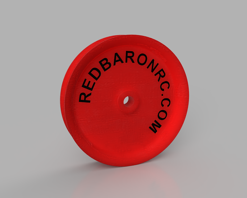
Infill: set to 100 percent.
If you are using lightweight PLA turn down the temperature so that these print with a higher density. You will have to up your extrusion percentage if you do this.
Supports: on.
The Tire:
Well this one is pretty obvious, its nothing but a torus, but it needs to be printed with flexible filament. The level of infill needs to be just enough to provide some rigidity, but not so filled that you cannot pry the tire over the rim. If you don't have the ability to print flexible materials then you can order the tires from us here: Alternately you can print them as a merged model in solid filament. See my video here about how to do this.

Lay the tire flat on one side.
Supports: on.
Covering:
At this point it's time to cover the center wing. Reference our blog on this subject here:
Don't put the wheels and tires on yet. I got ahead of myself in the pictures.
Once covered, dab some very thin ca glue over the covering at the holes where the landing struts will attach. then cut away the fabric so that the legs can be inserted later.
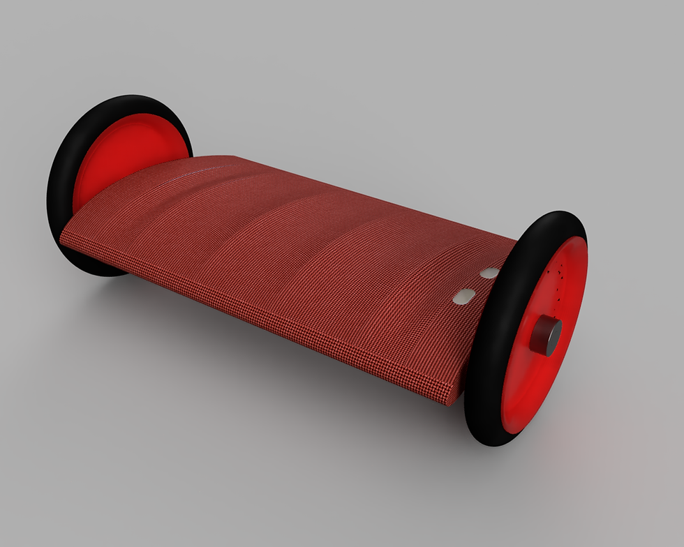
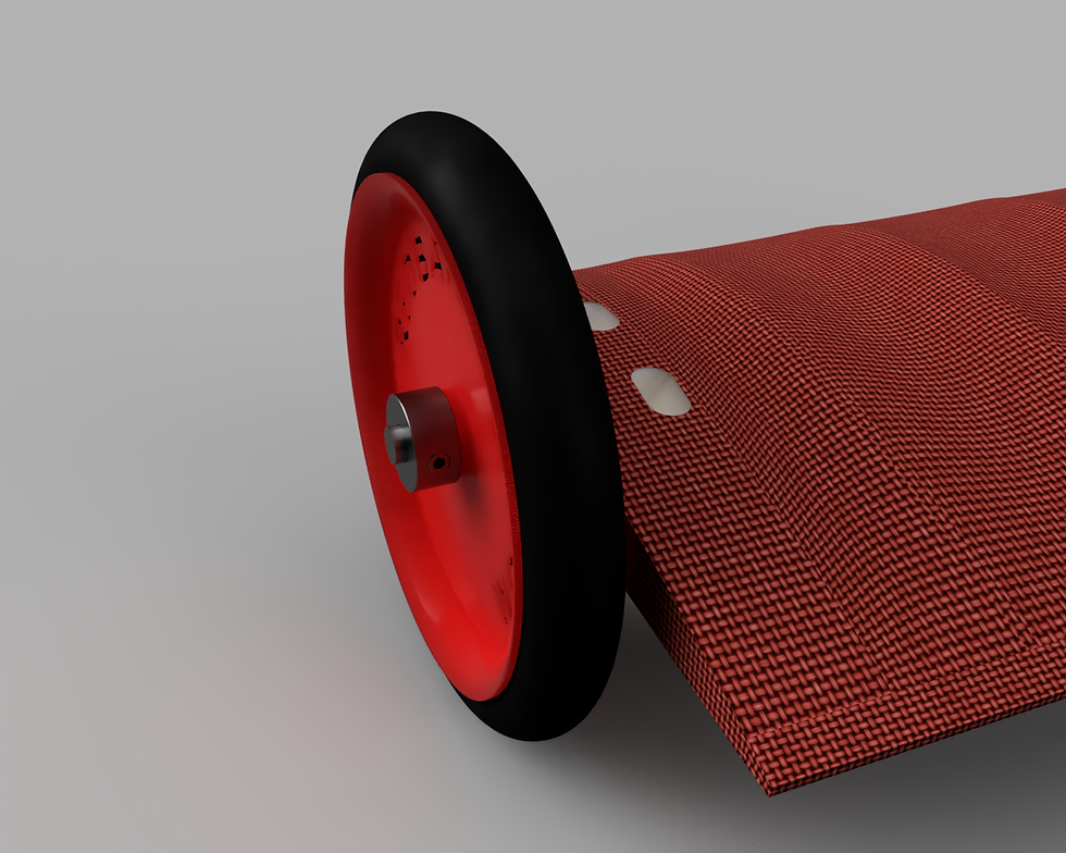
Wheel and Axle:
Now you can put the wheels on. Slide a 5mm dia. piano wire axle through the entire assembly. The wheels actually have a spacer on the inside of them to provide an offset from the wing. Provide a washer between the wheel and wing. On the outside attach a 5mm ID wheel collar as shown below.
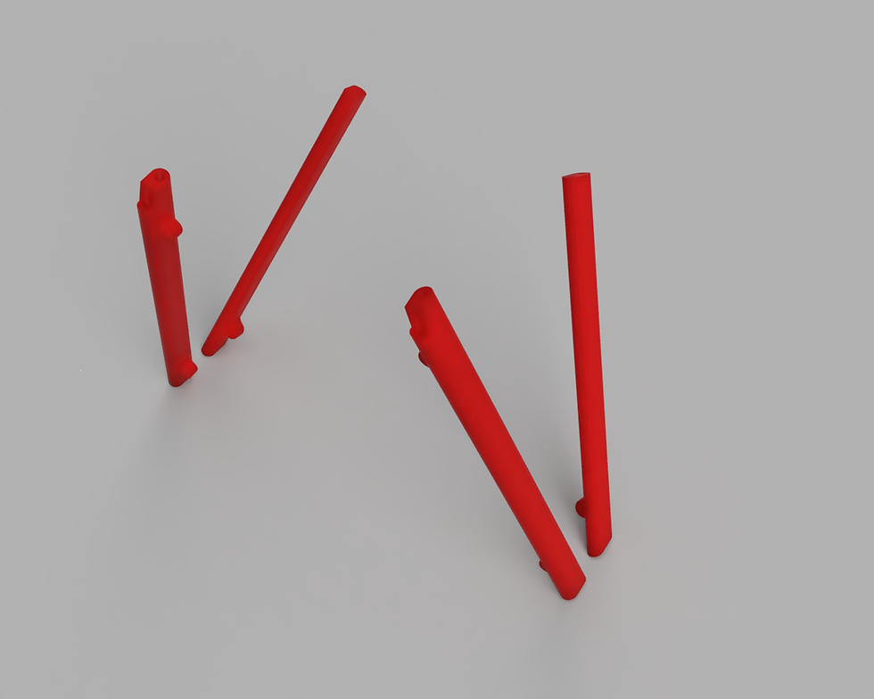
Gear Struts:
The gear struts consist of 4 separate prints. The front supports in the image below have the notch that mates to the firewall. Print each of these components flat on their back with the little eyelets facing upwards. Note the holes running through these struts. there will be a 2 mm. carbon rod inserted and glued into these struts after printing. Make sure that your horizontal hole offset value in your slicing software has this dialed in correctly otherwise you may not be able to get the rods to slide through after printing.
Infill: 100 percent on these. No need to use LW PLA on these. If you do, turn the temp down and increase your flow rate so that the density reflects more standard PLA.
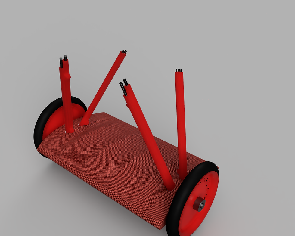
Strut Assembly into gear wing:
Below is the assembly all together. The carbon rods are shown for clarity. They will need to be trimmed as needed to fit into the mount holes on the lower wing and firewall. Do not glue them into place until you have the model all assembled so that you can ensure the gear is set perfectly straight on the model. As for the guy wires, Purchase a small roll of black Upholstery thread. Knot the thread through the eyelets and secure with a tiny dab of thin CA. This thread is significantly stronger than normal thread and can actually provide some level of lateral support even though its mostly just for looks.
That is it for the landing gear assembly! Check the main blog here for the next steps. Feel free to reach out to us with any questions. We will attempt to clarify the construction blog including your input as much as possible.


Comments