Electronics for the Mini Extra 300.
- Robareeno

- Jul 18, 2022
- 4 min read
Updated: Aug 26, 2023
Servo, Receiver, ESC, and Battery Installation.
Hinges:
All of the hinges for this model are created from a piece of clear packaging tape that is cut to a width of about 10 mm. This is easily accomplished by placing a pre cut length of tape carefully at the edge of a glass table top. Then simply run a razor blade down the edge of the table to get a perfect strip. Once cut, carefully place the strip onto the plane ensuring straight alignment. Once you are satisfied that you have it straight, insert the control surface to the opposite side ensuring that you have enough spacing to allow for full deflection of the controls. I find it helpful to fully deflect the position of the part before pressing the tape into place.
The next step is essential so do not omit this! The tape will only hold temporarily at best if left on its own. Turn the model over and deflect the control slightly in the opposite direction opening up space to work. Now generously run a bead of thin CA glue into the adhesive side of the tape at the hinge gap. The adhesive will wick under the tape to the model and create a really strong bond while allowing the tape to stay flexible at the hinge point. you now have a very clean, permanent hinge.
Elevator Connection:
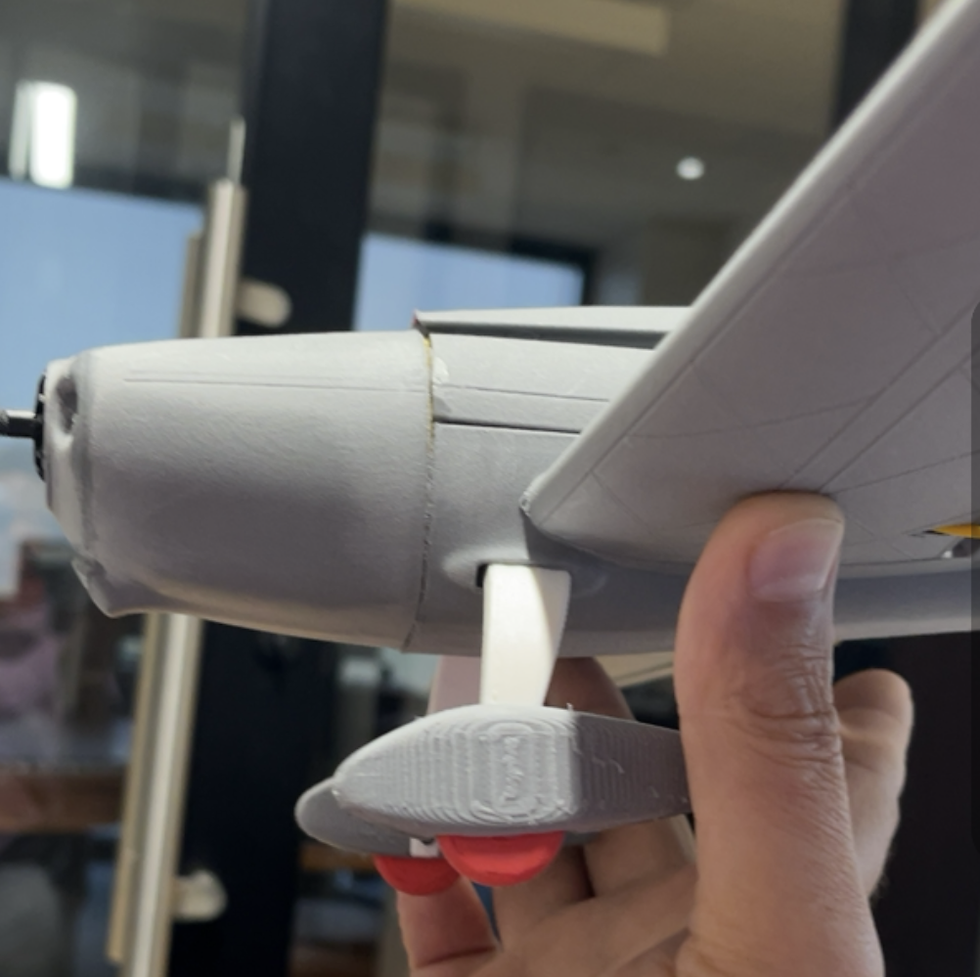
The image below is of the elevator connection to the control horn. The pushrods for this model are to be 1 mm. carbon rods due to the reduced weight. See Amazon Link here: You will notice in this view that the tail skid is also of this material. The control horns are of a two part design with the horn that can simply be CA glued into position, and the pushrod end that attaches with a tiny 1mm. machine screw. A single drop of carefully placed CA glue will eventually bond the carbon fiber rod to the pushrod end once you are satisfied that the servo position is exactly in the neutral position. Notice in this view that there is also a tiny 1mm Carbon rod reinforcement on the center position of the elevator for torsional strength.

Rudder Connection:
Repeat this process for the rudder.
Rudder and Elevator Servo Connection:
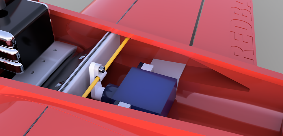
See the image below for the rudder and elevator servos. Because of the small nature of this model, the rudder servo uses an offset on the servo arm so that the pushrod can run over the top of the elevator servo.

Ailerons:
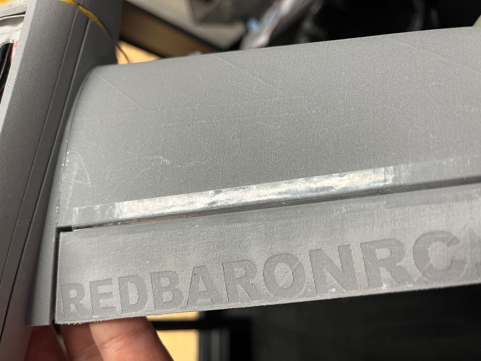
This is a closeup view of the horn we used for the Ailerons. The wings print with a tube guide within them so that a piece of 3D printer filament could act as a flexible pushrod back to the Aileron servo. This control horn is simply CA glued into position. Once the Aileron position is found at its neutral point, then CA glue the pushrod to the control horn as well.

The image below shows the aileron servo set in the servo mount inside the lower main fuselage. The flexible pushrod (filament) passes though the channel in one wing, through the eyelet attached to your servo horn, and then back through the other wing channel to the opposite aileron. Realize that once this is all in position, it is next to impossible to get out of this tiny area, so please ensure that your servo is actually in it's neutral position before buttoning this assembly all up. Don't be like me, I learned the hard way.
Wiring the ESC.
We recommend using a brushless electronic speed controller that has the capacity for up to a 4S battery and contains a BEC circuit to power your radio equipment from your flight battery. Verify the capacity of the motor and battery you chose to use to ensure that your ESC is not providing too much amps. Ideal prop diameter for this model needs to be 4" I have flown this model with a typical 3" 3 blade drone prop but it just looks funny and undersized. You must verify with your motor manufacturer if the motor you select can run a 4" propeller.
This is what I have repeatedly purchased for this:
Below: This size prop is a bit hard to find. We settled on these from Racedayquads.com See link:

For our prototype version, we used a Diatone Mamba 1408 motor but these are not as commonly available. Dimensionally the Diatone Mamba 1404 motor is similar.
You will notice in the pic below how the ESC positions loosely below the motor mount. The motor cowling slides over this, and holds it into position while allowing breathing and ventilation room.
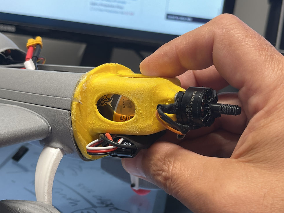
Our battery we settled on was a Tattu 4s 450 MAH Lipo.
The battery slides neatly into the compartment for it inside the motor mount.

Flight Controller
A model of this size is a handfull. A flight controller can tame it down a good deal. For it's size, we chose the Radiolink Byme A miniature flight controller.
The flight controller needs to be adhered with 2 sided tape to the top of the Aileron servo facing directly forward as shown in the pic below. We paired this with with an SBUS or ppm style receiver. that slips into the canopy area between the rudder and elevator servos. Click the image for a quick video on this.

.
Conclusion: That is it for the electronics installation! Check the main blog here for the next steps. Feel free to reach out to us with any questions. We will attempt to clarify the construction blog including your input as much as possible. Also please check out or new community forum. Feel free to post pics, ask questions, or help others.

Comments