Extra 300 Profile Main Fuselage
- Robareeno

- Feb 17, 2022
- 3 min read
Updated: Feb 23, 2024
Printing and Assembling the Fuselage
Update! March 15,2022.
You will now find two versions of the fuselage in your stl parts files. One version is the open web or trussed version that is depicted in the illustrations below, and the other is a complete solid body. If you don't wish to fuss with covering the model, opt for the solid body version. The printed parts are just barely heavier than the open web versions, but the difference is negligible on the finished model because no covering is required.
All of these parts are incredibly weight critical. They must be printed with lightweight PLA. It is my experience that I can print Colorfabb LWT filament with far less extrusion and thus lower weight than other lightweight filaments I've tried. Each part must be set flat on the build plate and follow my print settings. See my print settings on youtube
Main Fuselage component:
Print setting: "Solidbody LWT"

Horizontal Stabilizer:
Print setting: "Solidbody LWT"

Elevator:
Print setting: "Solidbody LWT"
Elevator Hinge:
The elevator and hinge is this fancy stuff called packing tape. It also is the horizontal stabilizer cover. It is easiest to install this before adding other components. It must be installed to the horizontal stabilizer prior to installing the vertical stabilizer. Make sure to allow for enough hinge space to allow for full deflection of the model. Apply the top layer on the model, then turn it over and carefully run a bead of thin CA glue down the hinge groove. The CA glue should be allowed to bleed under your packing tape, and will provide a significant bond. This single strip of tape is all you will need for a very strong gapless hinge. This is the same process for the rudder and Ailerons as well.

Detail of how a taped hinge assembly works:
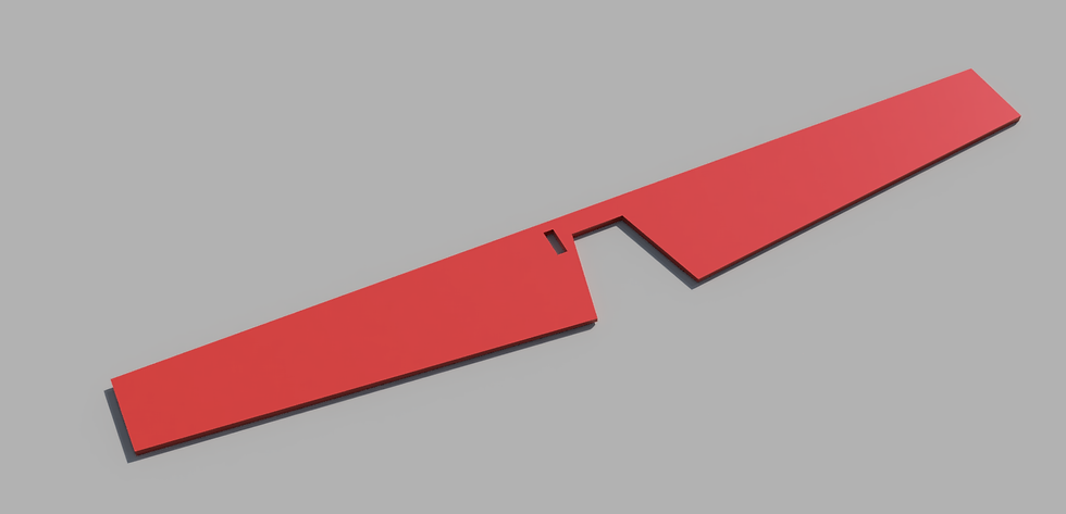
Forward Fuselage:
Print setting: "Solidbody LWT"

Empennage:
Print setting: "Solidbody LWT"

Assembly:

Vertical Stabilizer:
Print setting: "Solidbody LWT"

Rudder:
Print setting: "Solidbody LWT"

Landing Gear Mount:
Print setting: "Solidbody Rigid"
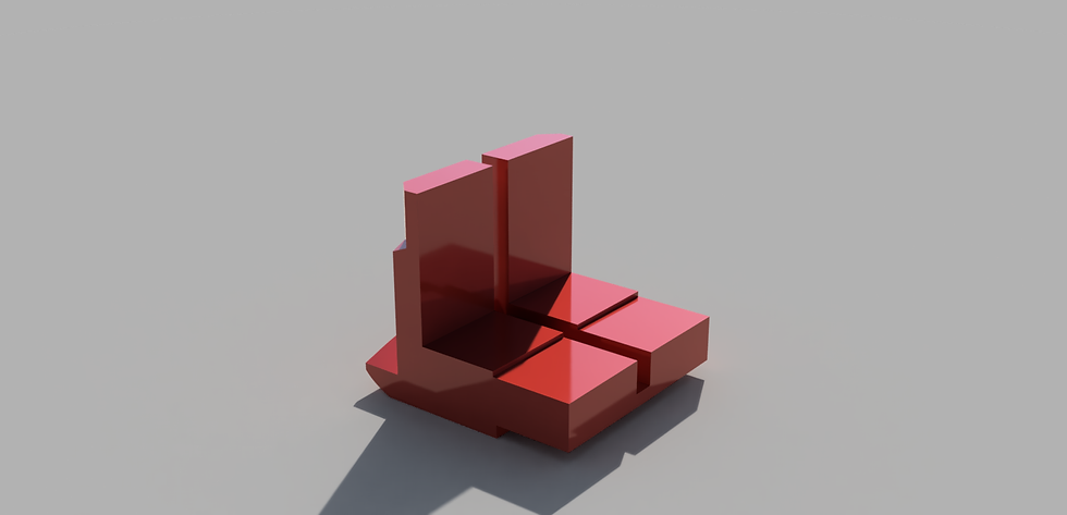
Landing Gear Mount Assembly View:
The mount slips over the forward fuselage and aligns with the back of the battery tray area. Note that the back of the landing Gear Mount also supports the wing center spar later.

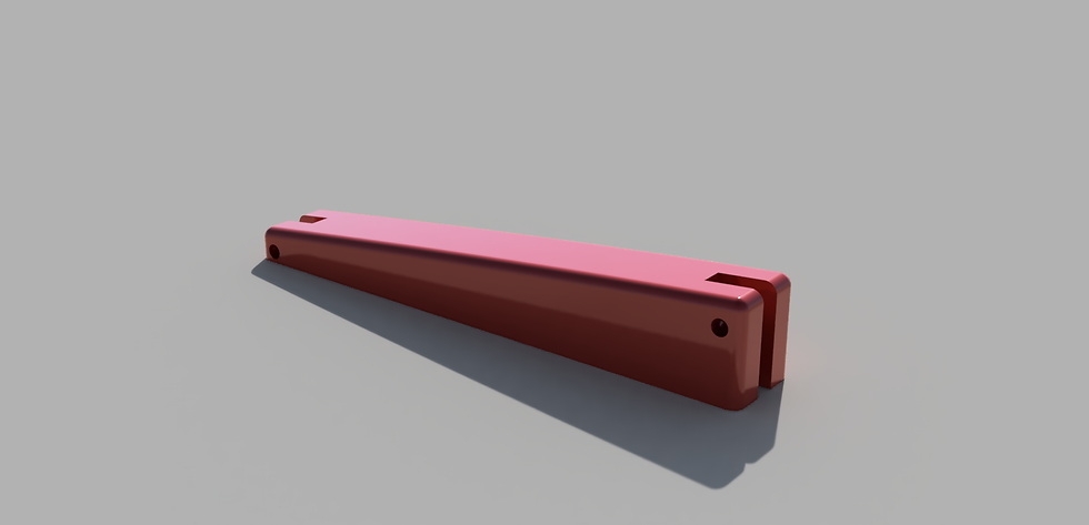
Landing Gear:
Print setting: "Solidbody Rigid"

Landing Gear Assembly view
in the holes provided, you will eventually mount the gear to the mounting bracket with two m2x12 screws. Wait to do this until the wings are attached.

Landing Gear wheels
The inside wheel pant can be CA glued to the landing gear leg. The wheel will then be supported by an M1.6x12 screw as an axle. A dab of thin CA glue on the outside of the threads should be sufficient to keep the axle in position. From there the outside wheelpant can be CA glued to the inside cover. Update on this. I started installing the screw from the gear leg side into the wheelpants. The tiny wheel spins freely on this and is only held in place by the opposing wheelpant.

Engine Mount:
Print setting: "Solidbody Rigid"
Assembly is straightforward in that it slides over the "plus" made by the front main fuselage component and forward vertical fuselage component. We recommend bolting the motor up prior to doing this.

Battery Hatch:
Print setting: "Solidbody LWT"
Conclusion: That is it for the Main fuselage! Check the main blog here for the next steps. Feel free to reach out to us with any questions. We will attempt to clarify the construction blog including your input as much as possible.

Comments